
[NOTE, OCTOBER 2023. The post below was written in April of 2016. What I wrote then stands, but since then I have discovered what I believe to be the solution to malfunctioning holding tank sensors in the vast majority of cases: hydro-jetting. Read my article about that here.]
I was recently faced with what may be the most ubiquitous problem in the world of RVing: a malfunctioning holding tank sensor system that incorrectly reports the fill level of the tanks. There are already a great many posts online about the subject with all kinds of suggested remedies. These include methods that attempt to clean the sensor probes by placing various solutions into the holding tanks, to rinsing wands that in some cases can be inserted into the tanks, to replacing the existing system with a new one of the same or different kind, etc. In my search for solutions I haven’t, however, come across information about locating replacement OEM sensor probes or installing them, and it took a bit of doing for me to locate some probes and information about installing them correctly. Sharing information on these latter two aspects of the problem is what motivated me to make this post. If all you want to know is where to get new probes and the correct installation positioning for them, then skip to Locating and Installing Replacement Holding Tank Probes (below). Because I could not possibly test all of the commercially available products marketed as solutions for this problem, most of which, IMHO, may be of little or no value, I am not providing extensive information about them, but I will provide some of my thoughts. Similarly, I could not test all of the home made tank cleaning liquids or methods although I will be providing my thinking on these too. While I had no way I could test all of the commercial offerings I will write about one item (below) that may prove invaluable to some people–it worked for me–the Valterra Master Blaster.
I have one idea of my own that I have not tested which is to attach a piece of paper towel or cloth to the short end of an Allen wrench (or something of similar shape) and once a probe is removed (if it is of the variety than can be removed) inserting the short end of the wrench through the probe hole into the holding tank and rotating it 360º in order to wipe the tank wall clean in the area immediately around the probe location. This may be enough to disrupt connectivity on the interior tank wall and get things working again, at least for a while. It would seem there is little point in replacing a KIB style probe because there really isn’t anything that can go wrong with one of these. Perhaps, the grommet could wear out and the tank begin leaking, but this wouldn’t be related to false level readings as far as I can see.
From what I gather the most common reason for false readings on the display panel is the build up of sediment on the inner tank walls that creates short circuits between the probes. There are other reasons that holding tank sensor systems fail to report tank status correctly, but it seems it’s usually caused by crud buildup on the inner tank walls. Before I decided to replace probes in my RV–something that in the end proved unnecessary–I tried to clean out my tanks by filling them about 2/3 of the way with soapy water and driving around for a while in order to slosh it about in the hopes that would wash away the problem sludge. At first that didn’t work even though I repeated the process a time or two (more on this below). I’d heard about other methods that include tossing ice cubes along with water and other ingredients into the tanks and driving around for a while so as to agitate the mixture. I did not try ice cubes for a couple reasons. First, there is no way I can get ice cubes into my gray tank and second, I’m not convinced that the action of the ice cubes knocking around would do much in the way of cleaning. Unless you pour several large bags into a tank it seems to me that all the cubes would do is float around near the surface of the water with a very small percentage of them knocking into the tank wall, possibly scuffing off a little bit of the sludge at the level where they are floating which may not be anywhere near the offending sensor(s). Plus, cold water is almost certainly not be the best for cleaning. I’m not saying there is no value to putting ice cubes in the tank, but I was and remain skeptical.
After I tried, unsuccessfully, driving around with soapy water in the tanks I decided to try the Valterra Master Blaster Tank Wand. This is essentially a hollow plastic pipe with a garden hose fitting on one end and a right angle nozzle at the other. It’s designed to be inserted down the toilet and to allow you to direct a powerful stream of water at all sides of the black holding tank, the idea being that of blasting off the sludge. With this tool I was able to successfully to clean out my black holding tank and get the sensor system for it working properly. I could not use it for my gray holding tank because the Master Blaster requires a straight pathway into the tank and the only pathways to my gray tank have bends of 90º or more preventing the use of this wand.

Before ordering my Master Blaster I spent a good while researching a number of different tank cleaning devices online including other wands similar to the Master Blaster and valves that attach to the end of the drain pipe so as to shoot water up the drain into the tank. One of these valve devices was the Valterra HydroFlush which comes in two models. I couldn’t see that it would do much more than shooting water into the bottom of the holding tank. Likewise for Valterra’s FlushKing and other reverse flush devices. If there were no bends in the drain pipe I could see that the attachments like these might spray some water on a small portion of the tank wall opposite where the drain pipe attaches, but I couldn’t see how it would do much else. To be fair, these devices aren’t really geared to cleaning tank walls, but rather flushing the tanks. These reverse-flush devices seem to me like a complicated way to pump water into a holding tank in order to just let it run out again. Why not just fill the tank from inside the RV by running the water? I suppose reverse flush devices might have more value if the intent is to dislodge a clog in a holding tank drain pipe, but for tank or probe cleaning? I just don’t see it. These devices seemed gimmicky to me and at least one product test video I saw seemed to confirm my suspicions.
I remain skeptical about much of what I’ve seen for various tank flushing hardware and chemicals and the advertising claims made for these products. Much of it made little if any sense to me, but the Master Blaster seemed to hold some promise if only for my black tank. My research on tank cleaning devices included watching a number of promotional as well as independent test videos showing various devices that either attached to or are intended for permanent installation into holding tanks. Most of these didn’t seem to do much if anything along the lines of cleaning the tank walls or probes. One device that requires permanent installation, Camco’s Tornado Tank Rinser, seemed to do a better job of tank wall cleaning than most other devices, but it requires at least 40 PSI of water pressure in order to make it work properly which could be a problem under some circumstances. Plus, depending upon RV construction and holding tank placement it might be difficult or impossible to install a device like this in a location where the spray it produces will reach all of the sensor probes. Due to the complexity of installation and use, as well as what I thought might be questionable efficacy I wasn’t sold on this device either.
It seemed clear that the Master Blaster put out a much more powerful stream of water than other devices that had spinning heads shooting out water jets, even those permanently installed into tanks. The video below by Mark Polk of RV 101 promoting Valterra products shows the HydroFlush and the Master Blaster. At about 2:45 into the video you can see how powerful the Master Blaster can be when used with a garden hose. That’s what I wanted: a powerful spray that I could direct toward all of the tank walls and the probes where it mattered!
Testing Probe Electronics
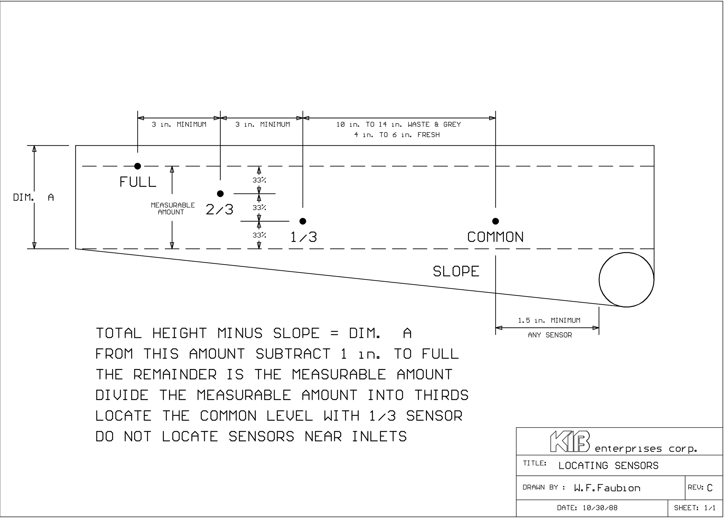
While the build up of gunk on holding tank walls seems to be the most prevalent cause of sensors behaving badly there is always the possibility that the problem originates elsewhere, with the electronics. I emailed Coachmen’s Service and Warranty Manager–a gent who has been enormously generous with his time and helpful to me the whole while I’ve owned my Freelander–and he gave me a method by which to test the holding tank sensing system electronics so as to determine if the malfunction was a problem with the circuitry or somewhere else. It goes like this: There are four probes embedded in the holding tank wall: one for 1/3 Full, one for 2/3 Full, one for Full and one which is a common ground. (See diagram, below.) Make note of which wire goes to which probe. (They should have different colors.) Disconnect the wires. Make sure the connectors on the end of each wire aren’t touching anything. Now, touch the Common (ground) and 1/3 full wire together. Attach them to each other with a clip of some sort to hold them in contact. Then press the respective button on the display panel and the 1/3 Full indicator light should illuminate. Next, add the 2/3 Full wire to the 1/3 and Common so that all three are in contact and check the display panel again. The 2/3 Full light should illuminate. Finally, add the Full wire to the others and check the display panel to make sure the Full light is illuminated. If the lights illuminate as they should then the electronics between the tank and display panel are OK. This will confirm that the problem of incorrect readings you get when the probes are connected originates at the probes. (There is a link below to the full, 6 page KIB troubleshooting guide.)
The tank probes used in my rig and I’m sure many others consist of a stainless steel threaded post (essentially a screw with a head that has no place for a screwdriver), a special rubber grommet, a washer and a couple of nuts. (See photo, below.) You could easily assemble one yourself from supplies at the hardware store if it wasn’t for the specialized grommet. My system in manufactured by KIB. I didn’t realize this at first but after being directed to KIB by Coachmen I noticed a tiny KIB logo at the bottom left corner of the display panel.

Locating and Installing Replacement Holding Tank Probes
I rather expect there are different kinds of sensor systems installed by RV manufacturers and there are after-market replacement probes such as the Horst Miracle Probe (now owned by Valterra). It may be that Horst probes are now standard OEM equipment on some rigs. The SeeLevel Monitoring System is another after market product, but this one has sensors outside the tank. They aren’t subject to internal sludge buildup but they may have other weaknesses. If I wasn’t planning on selling my rig real soon and if the last hot, soapy water rinse didn’t work for me I’d have tried the Horst Miracle Probes because they seem to work well according to user reports I’ve read and installing them would cost less and perhaps be easier than installing a whole new system such as the SeeLevel.
During the process of getting my system to work I spent a good long while trying to locate inexpensive generic probes online and coming up empty so I contacted the Service and Warranty Manager at Coachmen RV who advised me to purchase KIB Enterprises MP5 probes. A search online found prices from as low as 83¢ apiece at RVAutoParts ($11.54 for a set of 4 including tax and shipping) to as high as $28 for a set of four delivered. So, it may pay to poke around a little.
Information on properly installing the probes was even more difficult to find than the probes themselves. I noticed on my holding tanks as well as in many photos and diagrams I’d seen online that not only are the probes installed on the side of the tanks at different heights from the bottom of the tank (as you would expect them to be in order to sense different fill levels of the tank), but that they were also staggered from left to right. That’s the bit that was a something of a mystery to me. Still is. I know it has something to do with electricity but that’s out of my ken and since it wasn’t necessary for me to learn about the science behind this, I didn’t.
The included diagram (below) shows proper placement for the KIB MP5 probes. It’s worthy of some thoughtful study before drilling holes into the tank. You must consider not only the vertical and horizontal placement of the probes, but the distance from the drain and inlet(s). Drilling a hole in the wrong spot could leave you with the task of finding some method by which to repair the unwanted hole. That said, this ain’t rocket science, so there is some leeway in probe positioning. In some cases old probes may be removable and new probes inserted into the existing holes obviating the need to do any drilling, however, the Service and Warranty Manager at Coachmen told me that the probes in my rig were spin-welded in place and not removable. (Spin-welding is a process where two pieces of plastic are fused together by spinning one of them until heat generated by the friction between the two melts them together.) If you can determine that your probes are removable you may be able to locate a video on YouTube of a method for removing them. Videos come and go, but at the time of this writing there was one here. I think it might also be possible to remove an old KIB style probe by pulling on the grommet once the nuts are loosened, again, provided it’s not welded in place. I don’t know. I haven’t tried. I would leave one nut on the post at all times otherwise there would be some risk of the post falling into the tank.
The full, 6 page, PDF KIB troubleshooting guide is here.
Once an old probe is removed or a new hole drilled (3/8″ for the KIB probes as well as the Horst, if I’m not mistaken) the new probe (here I’m talking about the KIB probes) is pressed into the hole and the nut closest to the tank is tightened so as to squeeze the rubber grommet against the inside of the tank wall creating a watertight seal (see photo above). Then the wire connector is slipped over the post and the second nut is snugged over it to hold it in place. This may not be as easy as it sounds because there I observed a tendency for the threaded post to spin in place when the outer nut is being tightened or loosened. Tightening the inner nut may help prevent this. Another solution might be holding the inner nut stationary with a wrench but that may not be as easy as it first seems because the nuts are thin and the outer nut may also be covered by the wrench thereby preventing it from being turned. Yet another possible solution for this dilemma should it arise might be to replace the inner nut with a thicker one so that the wrench doesn’t extend above it. Another idea is to find a very thin wrench, one that is no thicker than the nuts.
Of course, you can avoid all of these problems by staying in a hotel, but where’s the fun in that? 😉
This blog takes an enormous amount of time and energy to build and maintain for which I am not paid. If you have found something useful or entertaining please consider using my affiliate link to Amazon.com when you shop there. Doing so will cost you no more and in some cases I may receive a small commission. Your support in the form of using my Amazon.com link or making a PayPal Donation will be greatly appreciated. Thank you.

Excellent information. I have searched many posts and this is the most technical and thorough that I have found. Thanks! Some photos of the tank/probe placement would augment the discussion.
Glad you found some value in the article. This post is one of, if not the most popular on my blog which testifies to the widespread nature of the problem and need for improvement in terms of RV systems.
Regarding your suggestion to provide photos of tank probe placement, please refer to the diagram I included in the article. It provides a clear illustration of how tank probes, in general, should be placed. Beyond that, it’s my understanding that holding tanks can be and sometimes are manufactured to fit in the space available. What I’m saying is that there are probably hundreds or thousands of different size and shape tanks in use. So, I’m uncertain how useful it would be to post a photo of one or two of them–it might be confusing to somebody who has a tank of a different shape. Then there is the matter of acquiring such a photo. The tanks on my current RV are not visible so there’s no way for me to create such a picture. Some images may be found online with a quick Google of something like “rv holding tank” and then clicking on the Image tab to see photos returned by the query. HTH.